
Views: 0 Author: Site Editor Publish Time: 2026-07-29 Origin: Site


Water ingress in commercial and residential concrete structures causes severe financial and structural consequences. Left unprotected, hydrostatic pressure forces moisture into concrete pores, initiating degradation, structural destabilization, and steel reinforcement corrosion through carbonation and chloride-induced reactions. When below-ground waterproofing fails, retrofitting or repairing the damage costs exponentially more than correct initial specification. For architects, structural engineers, and developers, these failures present immense liability risks and professional indemnity exposure.
This guide serves as a technical framework for evaluating, specifying, and implementing the correct Structural Waterproofing systems. By analyzing environmental data, structural design, geotechnical profiles, and international compliance standards, professionals can mitigate risks and ensure long-term structural integrity.
System Selection is Environment-Dependent: No single waterproofing method works for all structures; selection must be dictated by soil conditions, hydrostatic pressure, chemistry, and the intended use of the space.
Combined Systems Mitigate Risk: High-risk, deeply submerged, or habitable below-ground structures (Grade 3 environments) require a combination of Type A, Type B, and/or Type C systems to achieve acceptable risk thresholds.
Compliance is Non-Negotiable: Adherence to recognized structural standards (e.g., BS 8102:2022, ACI 515.2R, or equivalent regional codes) is critical for structural integrity, insurance backing, and warranty validity.
Early Specialist Integration: Engaging a qualified waterproofing design specialist (e.g., CSSW certified) during the initial architectural phase drastically reduces design errors, structural clashes, and lifecycle costs.
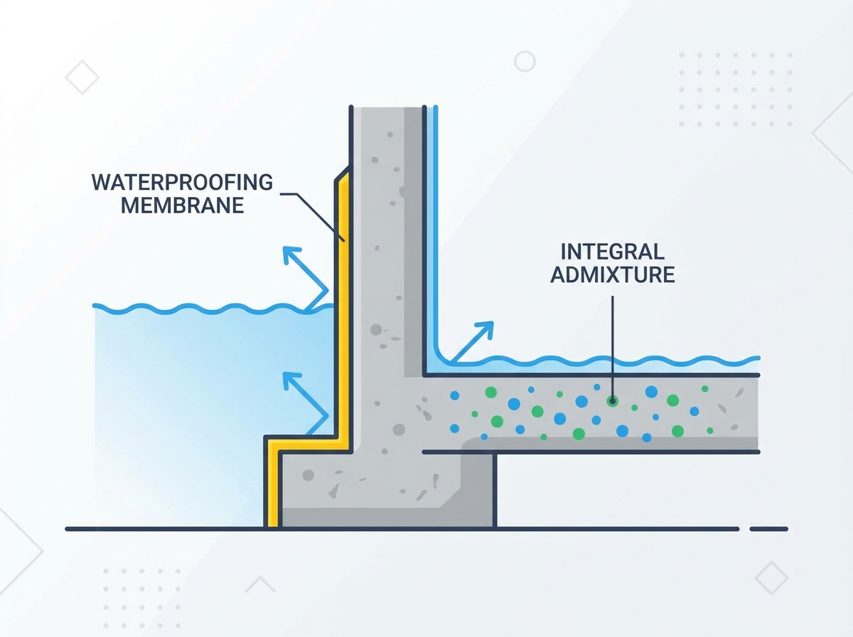
Protecting structures against water under hydrostatic pressure defines the core scope of below-ground water management. This applies primarily to below-ground, earth-retaining, or water-retaining structures. In contrast, damp proofing only protects against capillary action and soil moisture where no head of water pressure exists. Hydrostatic pressure increases with depth. Pressure rises by approximately 0.1 bar or 10 kPa per meter of water depth. This immense force pushes liquid water through microscopic concrete voids, demanding robust structural protection.
We often see confusion on site between these two concepts. Applying a simple damp proof membrane in a basement with a high water table guarantees failure. You must understand the site hydrology before specifying materials.
| Feature | Damp Proofing | Structural Waterproofing |
|---|---|---|
| Primary Threat | Capillary action, rising damp | Hydrostatic pressure, active water head |
| Application Area | Above ground, shallow slabs | Deep basements, retaining walls, tunnels |
| Material Thickness | Thin films, basic DPMs | Thick membranes, integral admixtures, cavity drains |
| Failure Consequence | Cosmetic damage, mold | Structural degradation, flooding, rebar corrosion |
Hydrostatic pressure forces water through concrete capillaries, construction joints, tie-bolt holes, and structural micro-cracks. This continuous moisture exposure triggers secondary damage mechanisms that compromise structural stability.
Reinforcement Corrosion: Carbonation and chloride penetration break down the alkaline passivation layer of steel rebar. This leads to expansive rust, spalling, and a critical loss of load-bearing capacity.
Freeze-Thaw Cycling: Water expands by roughly 9% within concrete pores during freezing, causing physical fracturing and surface scaling.
Efflorescence and Chemical Leaching: Free calcium hydroxide dissolves and migrates to the surface, weakening the cement matrix over time.
When you inspect an older parking garage, you often see rust stains bleeding through the concrete. That indicates active reinforcement corrosion. Once the rebar starts rusting, it expands, blowing off the concrete cover and exposing more steel to the elements.
Type A systems rely on the application of a continuous physical barrier membrane to the positive, negative, or sandwiched face of the concrete structure. Materials include pre-applied fully-bonded membranes that bond chemically with wet concrete, post-applied self-adhesive sheets like polymer-modified bitumen or HDPE, and liquid-applied membranes such as polyurethane or polyurea for complex geometries.
These barriers work best for shallow basements, retaining walls, and scenarios where external excavation is feasible. However, they depend heavily on perfect substrate preparation. They remain vulnerable to physical damage during backfilling, and a single seam failure can compromise the entire barrier.
Prepare the substrate by removing laitance and ensuring a smooth finish.
Apply the primer according to the manufacturer's specifications.
Install the membrane, ensuring all overlaps meet the minimum required width.
Detail all corners, penetrations, and terminations with reinforced liquid membranes or specialized tapes.
Protect the membrane with drainage boards before backfilling.
Type B protection involves designing the concrete structure itself to be water-resisting. This limits water penetration through advanced mix designs, reduced water-to-cement ratios, and meticulous joint protection. Admixture technologies include hydrophobic pore-blocking chemicals and crystalline active admixtures that react with moisture to self-heal cracks up to 0.4mm.
Engineered joint detailing utilizes active hydrophilic waterstops, physical PVC waterstops, and post-injected re-injectable hose systems. Type B systems suit deep commercial basements, civil engineering infrastructure, and high-water-table environments. Success requires flawless concrete placement, compaction, curing, and strict crack-width control.
Type C systems accept that minor water ingress will occur and manage it via an internal cavity drain system. Components include studded HDPE membranes applied to walls and floors, perimeter drainage channels, and sump packages equipped with dual pumps, battery backups, and high-water alarms.
This approach works exceptionally well for retrofitting historic basements, vaulted structures, and sites with unpredictable hydrostatic pressure. However, Type C does not prevent water from entering the concrete, potentially exposing reinforcement to damp conditions. It also requires ongoing lifetime maintenance, including periodic flushing of lime deposits and continuous power for the pumps.
Accurate specification begins with evaluating the site's water table classifications. Engineers must differentiate between low, variable, perched, and permanently high water tables using long-term monitoring data. Soil chemistry also plays a critical role. Aggressive soils containing high sulfates can cause cement attack, while chlorides promote rebar corrosion.
Additionally, acidic soils or the presence of radon and methane gas require specialized gas-barrier waterproofing. Ground permeability dictates water movement; silt and clay soils create perched water tables with slow drainage, whereas sand and gravel allow immediate hydrostatic head pressure.
Mapping structural use-cases to internal performance grades ensures the waterproofing system meets user expectations. Referencing BS 8102:2022 standards provides a clear framework for these environments.
| Grade | Description | Typical Use Cases | Performance Requirement |
|---|---|---|---|
| Grade 1a | Wet | Retaining walls, basic car parks | Some damp patches or dripping allowed. |
| Grade 1b | Damp | Plant rooms, basic storage | No water penetration, damp patches acceptable. |
| Grade 2 | Dry | Retail storage, workshops | No water penetration, no dampness. |
| Grade 3 | Habitable | Offices, residential, server rooms | Completely dry, controlled relative humidity. |
Relying on a single waterproofing system in Grade 3 environments carries significant mathematical risk. Formulating combined approaches mitigates these risks for high-risk profiles. Combining Type A with Type B provides a primary barrier against liquid water while the structural concrete acts as a secondary barrier limiting vapor transmission.
Alternatively, combining Type B with Type C ensures the concrete limits ingress to minor seepage, while the internal drainage safely manages any residual water. We always recommend combined systems for habitable spaces to prevent catastrophic failures.
Adhering to established codes ensures structural safety and compliance. BS 8102:2022 serves as the UK code of practice for protecting below-ground structures against ground water, defining design principles, grades, and risk analysis. In the US, ACI 515.2R and ACI 350 provide guidelines for specifying waterproofing and chemical-resistant barriers.
Meanwhile, Eurocode 2 outlines design rules for liquid retaining and containment structures. Following these standards protects against catastrophic failures and legal liabilities. You must document compliance at every stage of the build.
Clear delineation of professional roles prevents critical oversights. The structural engineer handles structural loading calculations, while the waterproofing specialist manages moisture control. Modern warranty providers mandate a certified design specialist, such as a CSSW professional, as part of the design team.
This single-point responsibility ensures the waterproofing strategy integrates seamlessly with the structural design, reducing clashes and long-term defects. When everyone knows their exact scope, the project runs smoother and risks drop significantly.
Understanding warranty types protects project investments. A manufacturer’s product warranty only covers material defects, whereas a professional indemnity-backed guarantee covers design and installation. Securing third-party warranty approval requires comprehensive documentation.
Detailed technical drawings showing all transitions and penetrations.
Product certificates like BBA, CE, or ICC-ES approvals.
Comprehensive site QA logs signed off by the inspector.
Photographic evidence of substrate preparation and membrane application.
Waterproofing systems frequently fail at specific critical details. Construction joints and day joints represent the highest-risk zones for water ingress, requiring active joint detailing like hydrophilic strips or injectable grouting hoses. Service penetrations, including pipe sleeves and cable entries, must utilize mechanical puddle flanges or expanding swelling sealants.
Structural formwork tie-bolts require cementitious structural repair plugs to prevent leakage. Furthermore, structural movement and expansion joints need flexible, heavy-duty systems like elastomeric expansion joint tapes to handle settlement and thermal expansion.
Poor substrate preparation remains a leading cause of membrane failure. The presence of laitance, curing compounds, form-release agents, or high moisture content in green concrete prevents proper adhesion. Acceptable substrate metrics must be met, such as concrete moisture content remaining below 4% for certain liquid-applied membranes.
Surface profile requirements should also match ICRI CSP guidelines to ensure maximum bond strength. We spend more time preparing the concrete than actually applying the membrane, and that effort pays off in long-term performance.
Rigorous on-site quality control verifies installation integrity. Electronic Leak Detection utilizes high-voltage and low-voltage methods to locate pinholes in elastomeric membranes. Holiday testing involves spark testing on non-conductive coatings to ensure continuous thickness.
Visual inspection and core testing validate concrete compaction, site slump tests, and overall compressive strength. Never skip the testing phase; finding a leak before backfilling saves massive amounts of time and money.
Effective structural waterproofing is essential for protecting buildings from water ingress, extending structural service life, and minimizing long-term maintenance costs. By selecting the appropriate waterproofing system based on site conditions, structural design, environmental performance requirements, and regulatory standards, project teams can significantly reduce construction risks while ensuring long-lasting building durability and safety.
To achieve the best project outcomes, consider the following recommendations:
Conduct detailed geotechnical and hydrogeological investigations before selecting any waterproofing solution.
Choose waterproofing systems according to the required environmental grade and project risk profile.
Ensure all construction joints, penetrations, and transition details are professionally designed and carefully installed.
Implement comprehensive quality inspections, leak detection, and on-site testing throughout the installation process.
With decades of expertise in advanced building materials and waterproofing technologies, CANLON has become a globally recognized provider of high-performance waterproofing systems and integrated building envelope solutions. Through continuous innovation, strong research and development capabilities, and rigorous international quality standards, the company delivers reliable waterproofing products that serve commercial buildings, infrastructure projects, industrial facilities, and residential developments across global markets.
From below-ground structural waterproofing and roofing waterproofing systems to complete building envelope solutions, CANLON provides comprehensive product portfolios, professional engineering support, customized project solutions, and long-term technical services. By combining intelligent manufacturing, sustainable product development, and customer-focused innovation, CANLON helps architects, engineers, contractors, and developers create safer, more durable, and energy-efficient buildings that perform reliably throughout their entire lifecycle.
A: Damp proofing protects against soil moisture and capillary action where no hydrostatic pressure exists. Structural waterproofing protects below-ground structures from water under hydrostatic pressure, which actively forces water into concrete pores.
A: High-risk or habitable below-ground spaces require combined systems to achieve acceptable risk thresholds. If one system experiences a minor defect, the secondary system prevents total failure and water ingress.
A: Type B involves designing the concrete structure itself to be water-resisting. This uses advanced mix designs, reduced water-to-cement ratios, specialized admixtures, and engineered joint detailing to limit water penetration.
A: Hydrostatic pressure forces liquid water through microscopic concrete voids, construction joints, and micro-cracks. This continuous exposure leads to reinforcement corrosion, freeze-thaw damage, and structural weakening over time.
A: Membranes typically fail due to poor substrate preparation, including the presence of laitance, curing compounds, or high moisture in green concrete. Poor detailing around joints and penetrations also causes significant failures.